Is there a description for “Developing reserved power interfaces” on unitree A1? The screenshot below is from the unitree A1 manual where section [16] shows the “Developing reserved power interfaces”.
The power connectors are described, but the two serial connectors in the middle are not. One of them should be connected to the controller board, because I get sensor data from the IMU, etc. Is this correct? I get nothing on the other serial port. What is the purpose of the other serial port? Is there a serial connection to the NVIDIA card?
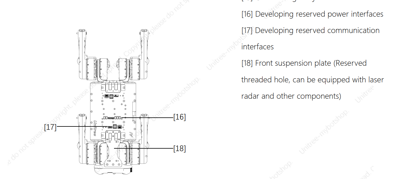
Section [16] outlines three distinct interface types:
The trio of ports on the right serves as auxiliary power outputs, offering the flexibility to energize various external sensors based on your specific needs.
The centrally located, white-colored connectors are designated for receiving motor data.
Positioned on the left are two ports intended for external power input.
Two ports on the left are for external power input.
Unfortunately we don’t have any additional information on them “Developing reserved power interfaces” but as I know correctly, these ports can be used power additonal sensors / devices: Quick-Start — A1 Tutorials 1.0.0 documentation@Azib could you please double check and may add a picture to the docs and forum?
Regarding the Serial Connection you are right. We are not 100% sure, but I would say one port is for flashing the MCU (manufacturer Interface / don’t having access on it) and the other for getting raw MCU datas etc.