Could you please provide the part number (if available) and explain the function of this diode in this context? Currently, we are able to start the Husky and receive the ROS2 topics, but the communication indicator does not turn green, and we are unable to drive the Husky.
Hi,
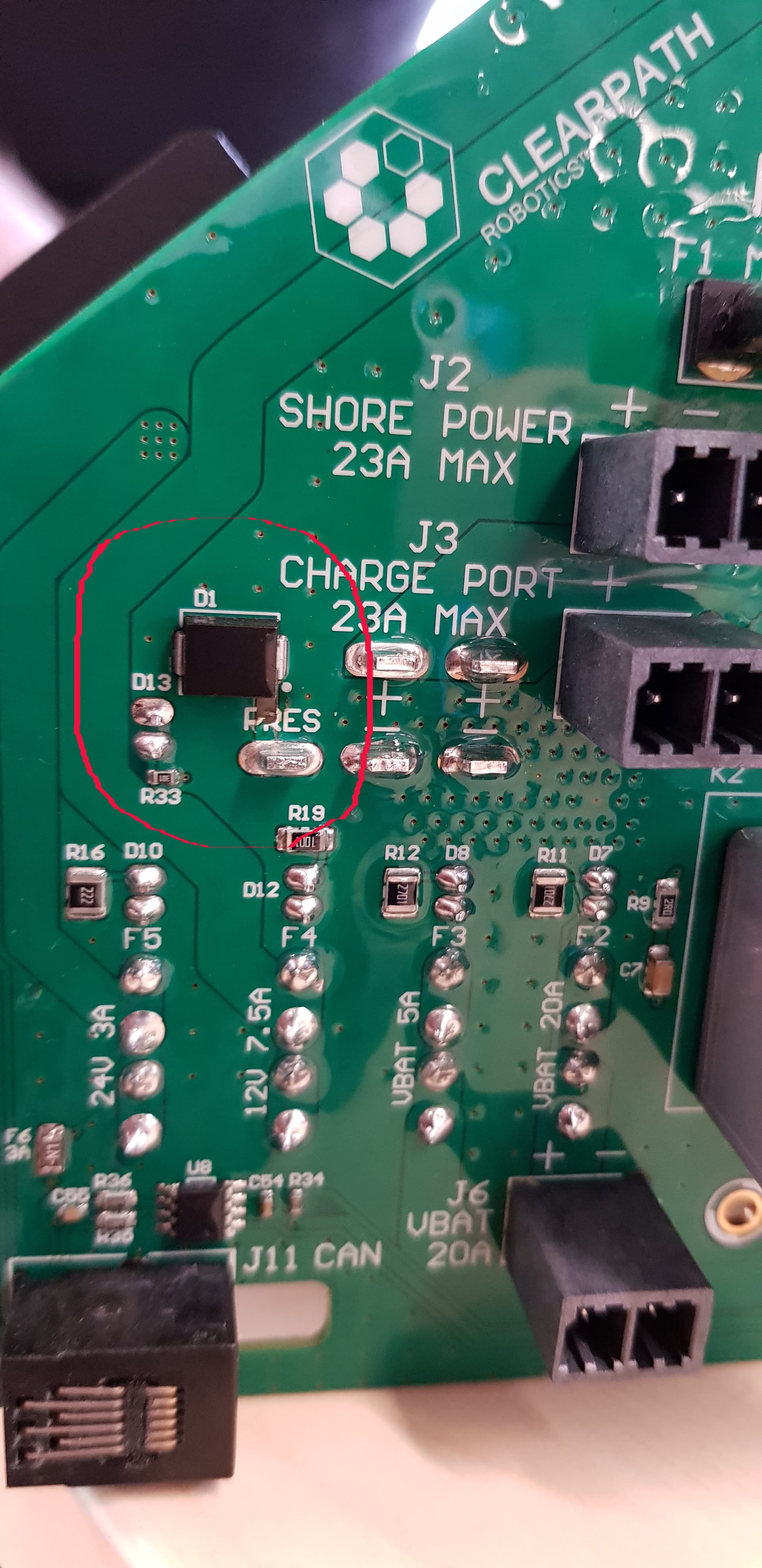
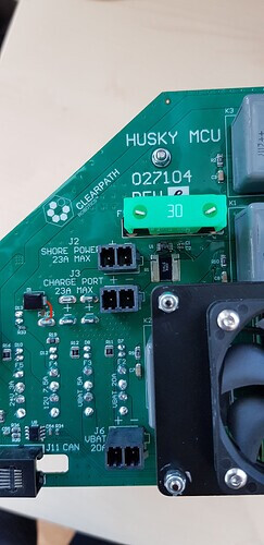
Could you please check if D1 and the solder joint are connected (see the red line below), assuming you have a similar board available?
We can’t detect any connection. The trace may be damaged or burnt.
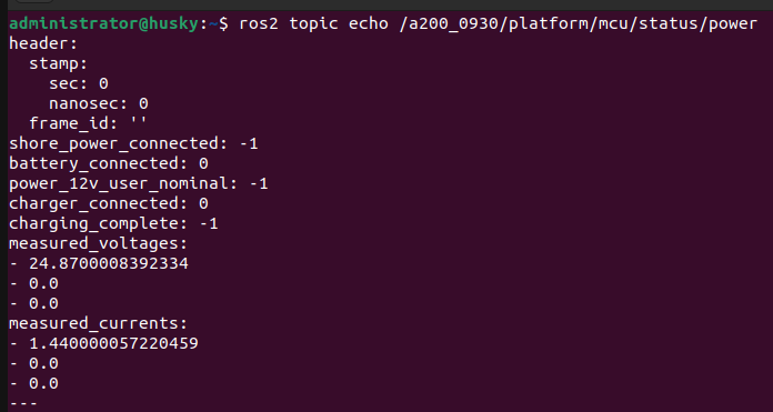
Yes, we have checked all the fuses, and they are all intact. All the LEDs are on, and the heartbeat indicator is working fine. The topics are being displayed, and all connected devices (USB hub, LiDAR, etc.) are functioning. However, the COMM indicator doesn’t turn green, and the Husky doesn’t drive.
f you have a circuit diagram or the physical board, it would be helpful if you could check whether there is a connection between the diode and the connector (see the red line below). The forward voltage drop across the diode is approximately 0.57 V (is it correct?).
Hi, unfortunately, for that, you have to contact Clearpath. However, from the service, everything should be working. @Azib could you give SAL clearpaths email for support?
"The D1 diode is a part of the part sense circuit, if it has failed, it could be an indication that a reverse voltage was applied to the battery connector. Would it be possible to follow up with the client on the circumstances leading up to the diode failing?
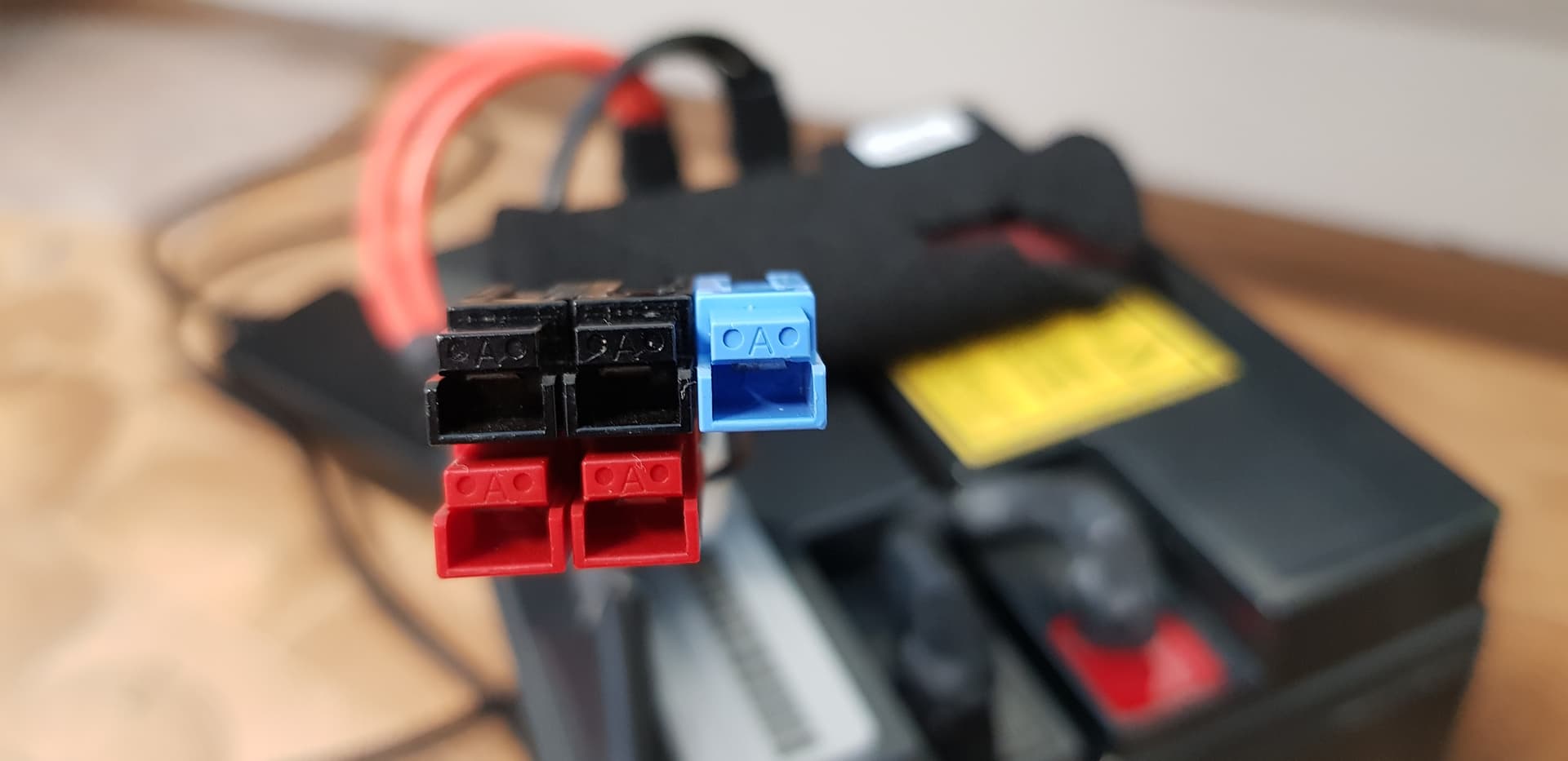
Ensure that they did not inadvertently connect the battery in the wrong orientation.
Ensure that the battery is healthy (i.e. good state of charge, can supply current normally, etc.)
In the image it appears that the trace to the battery sense lug has become exposed. Has this client replaced or worked on this MCU in the past?
The part number for a replacement D1 diode is SMCJ5.0A (Example source: SMCJ5.0A Littelfuse Inc. | Circuit Protection | DigiKey) Bear in mind that if you proceed with this the warranty on the MCU board, if it is still valid at this point will be void."
As expected, connecting the trace to the battery sense lug resolved the issue. However, we are still unsure why a reverse voltage was applied to the battery connector in the first place.
Please note that the Husky has been stored indoors in a dry environment throughout.